A brief introduction and system design description of the linear sliding unit:
◎Linear sliding units are also called linear rails, sliding rails, linear guides, linear sliding rails. They are used in linear reciprocating motion applications. They have a higher rated load than linear bearings, and can bear a certain torque at the same time, which can be used under high load conditions. Realize high-precision linear motion.
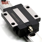
The linear sliding unit is divided into a square ball linear sliding unit, a dual-axis core roller linear sliding unit, and a single-axis core linear sliding unit.
In the mainland, it is called a linear slide unit, and in Taiwan it is generally called a linear guide or a linear slide.
The function of the linear motion guide is to support and guide the moving parts to make a reciprocating linear motion in a given direction. Depending on the nature of friction, linear motion guides can be divided into sliding friction guides, rolling friction guides, elastic friction guides, and fluid friction guides.
◎Linear bearings are mainly used in automated machinery, such as machine tools imported from Germany, paper bowl machines, laser welding machines, etc., of course, linear bearings and linear shafts are used together. Linear sliding units are mainly used for accuracy requirements comparison On the high mechanical structure, the slider-makes the movement change from a curve to a straight line. The new guide rail system enables the machine tool to obtain rapid feed speeds. In the case of the same spindle speed, rapid feed is the characteristic of the linear sliding unit. The linear sliding unit is the same as the flat guide rail. It has two basic elements; one as a guide is a fixed element, and the other is a moving element. Since the linear sliding unit is a standard component, it is a machine tool manufacturer. The only thing to do is to process the plane of a mounting rail and adjust the parallelism of the rail. Of course, in order to ensure the accuracy of the machine tool, a small amount of scraping of the bed or column is essential. In most cases, the installation is relatively simple.
The guide rail as the guide is hardened steel, which is placed on the installation plane after fine grinding. Compared with flat guide rails, the cross-sectional geometry of linear sliding units is more complex than flat guide rails. The reason for the complexity is that grooves need to be machined on the guide rails to facilitate the movement of sliding elements. The shape and number of grooves depend on the requirements of the machine tool. Completed function. For example: A guide rail system that bears both linear force and subversive moment is compared with a guide rail that only bears linear force. The design is very different.
There is no intermediate medium between the moving element and the fixed element of the linear sliding unit, but a rolling steel ball. Because the rolling steel ball is suitable for high{{0}}speed motion, has a small friction coefficient and high sensitivity, it can meet the working requirements of moving parts, such as the tool holder and carriage of the machine tool. The basic function of the fixed element (guide rail) of the linear sliding unit system is like a bearing ring. The bracket for mounting the steel ball is shaped like a "v". The bracket wraps the top and both sides of the rail. In order to support the working parts of the machine tool, a set of linear sliding unit has at least four supports. Used to support large working parts, the number of brackets can be more than four. When the working parts of the machine tool move, the steel balls circulate in the groove of the bracket, and the wear of the bracket is distributed to each steel ball, thereby prolonging the service life of the linear sliding unit. In order to eliminate the gap between the bracket and the guide rail, the preload can improve the stability of the guide rail system and the preload can be obtained. It is to install an oversized steel ball between the guide rail and the bracket. The diameter tolerance of the steel ball is ±20 microns, with 0.5 micron increments. The steel balls are screened and classified and installed on the guide rails respectively. The size of the preload depends on the force acting on the steel balls. If the force acting on the steel ball is too large, the steel ball will withstand the preload for too long, which will increase the movement resistance of the bracket. There is a balance problem here; in order to improve the sensitivity of the system and reduce the movement resistance, the preload must be reduced accordingly, and in order to improve the movement accuracy and the retention of precision, it is required to have sufficient preload negative numbers, which are contradictory two. aspect.
If the working time is too long, the steel ball begins to wear, and the preload on the steel ball begins to weaken, resulting in a decrease in the movement accuracy of the working parts of the machine tool. If you want to maintain the initial accuracy, you must replace the rail bracket, or even replace the rail. If the rail system has a preload effect. The accuracy of the system has been lost, and the only way is to replace the rolling elements.
The design of the guide rail system strives to have the largest contact area between the fixed element and the moving element. This not only improves the carrying capacity of the system, but also the system can withstand the impact force generated by intermittent cutting or gravity cutting, spread the force widely, and expand the bearing capacity. The area of force. In order to achieve this, there are various groove shapes for the guide rail system. There are two representative ones. One is called the Gedai type (pointed arch type), the shape is the extension of a semicircle, and the contact point is the apex; the other The species is arc-shaped and can also play the same role. No matter what kind of structure, there is only one purpose, and strive to have more rolling steel ball radius contact with the guide rail (fixed element). The factor that determines the performance characteristics of the system is: how the rolling elements contact the guide rail, which is the key to the problem.